
Forums › Laser Resources › Laser Physics Related Literature › Hydrokinetics Article
- This topic is empty.
-
AuthorPosts
-
lagunabbSpectatorDr Bornstein:
The question needs to be addressed in sequence simply because of the way the data was interpreted. My first question is:
1. The authors apparently based their conclusions on the depth of ablation rather than mass (volume if you assume the bovine enamel is homogeneous in density) unlike other researchers like Hibst (his 1997 paper for example). If you buy the authors’ approach then the discussion and interpretation are as written. If you buy the Hibst (and others) approach, the volume ablated would be the correct approach to analysing the data. Which is the proper approach? If you accept the author’s approach, no further discussion is needed. If you believe the Hibst approach, the data becomes more interesting and we can discuss further.
(Edited by lagunabb at 6:25 pm on Sep. 30, 2003)
Robert Gregg DDSSpectatorQUOTEQuote: from lagunabb on 9:10 pm on Sep. 30, 2003
Dr Gregg:My beef is that you presented to me (and I assume others) something as data to be trusted when you knew there were problems with that data. Am I now suppose to be able to draw the line where your data can be trusted or not? What is data and what is not?
You have a nice system from what I have read but does that make it OK to knowingly present erroneous data once in a while.
Ok, I see you are going to ignore the science and research I presented in my last post (kinda like you do with Dr. Bornstein’s science), and continue to pick on one case example that seems to justify your continued personal attacks and distractions from the HKS controversy. Nice political science debating strategy, but not especially convincing to your laser science arguements in the written journal that is being created herein.
A single x-ray or patient example is not “data”.
It was in a case study example, not a body of evidence. (The SPIE paper is a body of evidence). It was a comparative x-ray that morphed the before and after images–which to any dentist looks impressive w/o the Emago® comparisons.
It is a bit of a stretch to assign trustworthiness to one x-ray that reports what it reports–visual imagery of bone dentisty changes consistent with other bone density analysis and now histology. If anything, the x-ray in question is now vidicated as well.
It was a clinical case presentation that discussed the clinical parameters of healing along with the radiographic and comparative Emago® x-ray that give the x-ray you question its (really my) credibility.
Here’s some excerpts from the paper regarding the image you inaccurately call erroneous:
Patient was seen at 60 days. The chart records states, “Periapical x-ray of #20 shows periodontal regeneration including PDL and bone. OHI is excellent. BOP is minimal. Patient reports are excellent regarding the subjective and objective symptoms and signs. Patient is using Proxibrush regularly with excellent results.”
Mean Probe Depth Changes (MPDC) are computed by finding the mean of the differences in probing depths from baseline to follow-up. MPDC of tooth #20 at 14 months post-treatment reduced an average of 4.5mm or 50% pocket depth reduction with no recession. The 4.5mm MPDC in this patient is consistent with a 4.5 MPDC for pockets > 8 mm reported in a previous LPT case report of 4 patients(7), and over 1900 probing sites in 42 patients in a retrospective, multi-centered, private practice study(8).
That references this case study with clinical data of a peer reviewed published paper that you failed to mention in response to my last post, or the Dentistry Today article.
And here’s the actual radiographs. To a trained clincian, the 2 dimensional improvement is impressive enough, AND consistent with the 3-D Emago® Gray scale morphed image. It is neither erroneous, nor exaggerated. It gives a 3-D perspective to the 2-D x-rays.
[/i]
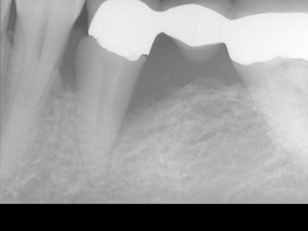
Figure 2. Pre-Operative x-ray
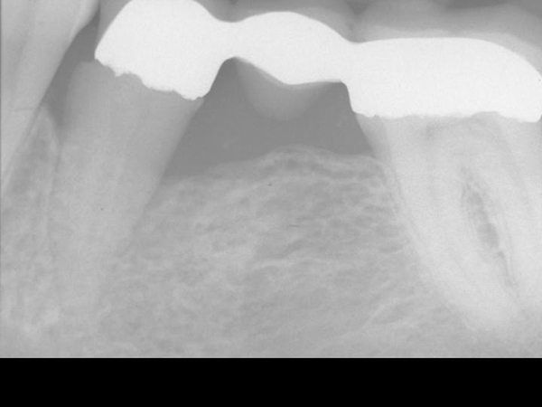
Figure 3. 14 month post-operative x-ray
[/i]
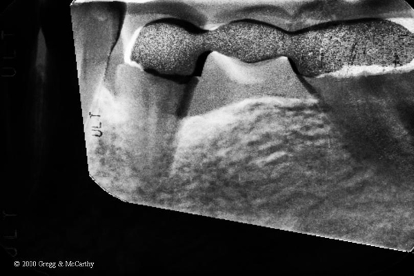
Here’s the exact caption to Figure 4.
Figure 4. Gamma correction of the before and 14 month post-operative x-ray using Emago® software(16). White areas indicate increased bone density. Bone density increases extend circumferentially and 3-dimentionally into the alveolus.
And here’s the text:
The Gamma Correction contrasts(16) in Figure 4 demonstrate the elimination of the mesial and distal bony defect and a marked increase in radiographic density interproximal to teeth number 19, 20, and 21—indeed, throughout the alveolus and into bone.
The problems mentions with the Emago® software were NOT that the data was erroneous, but that it was difficult to pick the 4 separate data points to be the same on each x-ray compared–which caused “noise” in the images, not in their proportion.
The images you selected as representative have the same “noise” as in the Emago® software. (Look at all the flecks of green that any clinican knows can’t be part of the before and after comparison. That sort of noise can be reduced, but not eliminated, as your example illustrates. That doesn’t make the area being examined erroneous or the data false.
Attacking the personal credibility of others, mis-directing the attention of others from the topic of discussion is a often used tactic in this political season. But that should be reserved for politicians. This is a professional website and such antics have no place here.
I have posted the x-rays to the specific challenge to my professional integrity and trustworthiness (again).
We clearly need a dental professional to make the analysis and interpretation and explain why the regeneration of bone in the after x-ray is so impressive. And, then why it is so important that histology was undertaken to validate the radiographic impressions.
Check Mate
Robert H. Gregg, DDS
ericbornsteinSpectatorBob:
Nice images.
My read on the x-rays is a clear 2mm GAIN in bony height around the mesial defect presented, and a 3+mm GAIN in bony height around the distal defect presented. Pretty damm good for not using graft and/or membrane.
From a microbiological point of view, I have this to say.
We all should think of periodontal pockets as unique gram negative ecological niches that are very difficult to eradicate with traditional periodontal scaling and root planing. If only a few recalcitrant periodontopathic bacteria are left in a pocket, you can have a regrowth of over 1 million organisms within a 24 hour period. Especially within an area that is 37C with plenty of fluid and nutrients available for the bugs.
If the laser is successfully vaporizaing enough periodontopathic bacteria (and I believe it is), the immune cells in the bleeding area should take care of the rest. Also (and possibly more importantly), many of the osteolytic enzymes present from the IGA,IGG,IGE and macrophages in the area (the normal immunological response seen in a periodontal pocket) to combat the periodontopathic microorganisms will be completely inactivated and denatured by the heat of the infrared pulses.
This means good bye OSTEOCLASTS and hello OSTEOBLASTS.
Obviously, the laser is creating an environment that will allow the healing process to begin almost immediately, and close the pocket.
With no area for the bugs to colonize in an anaerobic environment, (ie their unique ecological niche is eliminated as the tissue reattaches to the cementum) many far less pathogenic gram positive aerobic organisms will colonize the new healthy sulcus (2-4mm) and the periodontal problem problem is solved.
This is in my view, a far better mechanism than letting an antibiotic vector (gel, spheres, chip) sit in the sulcus for up to 21 days, and inhibit the tissue from reattaching.
It is simple logic, that two things cannot occupy the same space at the same time. Also, there is no resistance to the laser, unless the bugs have SPF 1,000,000 sunscreen in their beach bags.
Nice case.
Eric Bornstein DMD
lagunabbSpectatorDr Gregg:
I have no problems with the Yukna histological study but I was talking about your paper on your patient. I am having great difficulty understanding your continued assertion that 3D data or interpretations can be obtained from differencing 2D x-rays. A correctly done difference would show density differences in 2D where they actually occurred (with some noise) instead of everywhere like in your Figure 4? Or are you now saying there is noise everywhere in Figure 4 but no noise around the tooth?
Robert Gregg DDSSpectatorEric,
Excellent analysis!
Your exceptional dissection on the mechanism of action is very close to what Del, Prof Yukna and I have theorized , with a few other things in mind such as release of bone morphogenic proteins (BMPs), and pre-cusor cells differentiation in bone, but you suggest that with your comment regarding osteoblasts.
This is an area that I can better follow your musing.
From the patient’s chart
Pre-Op Probe Depths (1994) Post Op Probe Depths (2000)
MF – 7mm MF – 5mm (+2mm)
CF – 5mm CF – 5mm (0mm)
DF – 12mm DF – 5mm (+7mm)ML – 9mm ML – 3mm (+6mm)
CL – 9mm CL – 3mm (+6mm)
DL – 12mm DL – 6mm (+6mm)We agree, Eric, that it is optimal if no foreign material are placed into the pocket that the body has to “compete” with to properly populate the root with cementoblasts. Two things can’t occupy the same space, AND if they try, there will be an exaggerated inflammatory response that inhibits regeneration.
Ray, The density changes do show where they actually ocurred. It’s not noise but bone density changes we interpret with those changes. Noise would be outside the quadrangle that was “selected” when the image was created–like the metal in the bridge.
The entire area below and outside the area of the tooth and pocket defect has increased in density as well from the comparative image. That’s frequently seen when one places a bridge (better than the one here) as piezo electric currents stimulate a “hump” in the bone between the two abutment teeth. What I think we are seeing in this comparative image is an hyper-response of the bone through that region in response to the LPT and the OCCLUSAL ADJUSTMENT that was done simultaneously to relieve the pressure on the bone which was activating the osteoCLASTS.
It’s one Emago comparative radiograph that in the context of the before and after x-ray and the probe depth data, support the understanding of the 3-D nature of the defect, i.e. circumferential versus “mesial” and/or “distal”.
This tooth was vertically compressible in the alveolus (tooth socket). It bobbed up and down like, well, an oil “horse”. It is therefore impossible for this to be a 2 wall (2-D) defect. This comparative radiograph helps the viewer with that perspective.
We never published another comparative x-ray image other than this ONE using this Emago gray scale imaging (we have a bunch), because we were unsatisfied with the consistency in what we were seeing.
This one and ONLY one image was used not to validate Emago Gray scale imaging, but to give perspective to the clinical findings and the x-rays they were published with.
At least we were trying to present some science where there was none to be had. It was the best we could do at the time, and should not be cause for impugning our credibility or integrity.
Others should make such attempts in support of their clinical claims, and I will applaud them, not attack them.
Peace……..
lagunabbSpectatorI guess my evaluation may have been too harsh. I came from a background where laboratory notes and measurements on experiments have to be reviewed and co-signed by 1-2 levels of management and where journal papers have 3-4 levels of technical peer review. We also occasionally call out the firing squad when someone represents qualitative data as quantitative data (intentionally or not). With all the discussions here and on dental town, I have seen mostly qualitative observations and my backgound makes me uneasy and more skeptical compared to others that have spent their life in dentistry. Give me time and I may become more tolerant.
Peace
lagunabbSpectatorHere is the reply from Dentsply regarding my request for tensile, compressive and yield strengths. Only failure by bending (tensile failure) is measured:
=======================================
I just received your request through our Tecnical/Marketing department. For dental porcelain material, there is no yield strength available as in metal since porcelain material does not “yield” under stress. We do not measure its tensile or compressive strength, either. Tensile strength is usually for metal. Rather, we measured its flexural strength in the
3-point bending mode. The failure of the porcelain, however, is under
tensile stress. I have attached below a porcelain properties table for three of our porcelain products for your reference.The strength in the table is the flexural strength based on the test that I described above.
(See attached file: Porcelainpropertiescomparison.doc)
======================================Bending failure data below:
Properties Ceramco II Finesse Ceramco3
Firing temperartureopaque:975°C, dentin:940°Copaque:800°C, dentin:760°C opaque:975°C, dentin:960°C
Strength (ISO6872)70 MPa84 MPa67.5 MPa
Thermal expansion coefficient12.5 ppm/°C @ 500°C11.8 ppm/°C @ 430°C12.8 ppm/°C @ 500°C
Dilatometric softening point642°C555°C620°C
Glass transition temperature513°C465°C525°C
Hardness (Vickers)570 kg/mm2617 kg/mm2570 kg/mm2
Leucite content (wt%)43%8%35%
Leucite crystal size (µm)8 – 10 µm2 – 3 µm8 – 10 µm
Bond strength (ISO9693)39 MPa (Degudent SF)38 MPa (Degudent SF)38 MPa (Degudent SF)
Chemical solubility (ISO9693)17 µg/cm224 µg/cm225 µg/cm2(Edited by lagunabb at 12:29 pm on Oct. 9, 2003)
SwpmnSpectatorRay:
So no feedback on the compressive strength figure I presented.
Al
lagunabbSpectatorNo feedback. Their reason for not measuring those numbers is that dental procelains fail in bending mode. I have no idea whether that bending failure is a reasonable assumption. Just thinking out loud — if you think about the way a tooth chips (like mine did at a young age), it was bending because I tripped face down and the impact of the tooth with ground would result in bending. But how about molars?
SwpmnSpectatorYou’re on the right track and it’s fairly common to see porcelain fractures on molar and premolar(posterior) crowns. Dentists are taught to build posterior teeth crowns so that they do not contact as the patient grinds side to side and as the mandible moves laterally during chewing. The front teeth(canines/incisors) are supposed to take the back teeth out of bite as the mandible shifts. Reason being it is a generally accepted concept that contact of posterior teeth during grinding or chewing may result in trauma to the jaw muscles and the temporomandibular joint structures. However, patient’s bites change over time, some patients have “group function” where the molars do contact on lateral movements and in the real world its not always possible to correct all of a patient’s bite problems($$$). Therefore, there are many instances where posterior teeth porcelain crowns wind up in contact during lateral function and are thus subjected to tensile bending stresses.
Al
P.S. I do hope this post does not seem oversimplified but as many of your engineering/materials posts are over my head I don’t know your level of understanding of dental occlusion
lagunabbSpectatorI have been conversing with Dr. Zhigilei of U. of Virginia regarding enamel ablation. We have similar thoughts regarding the current state of research. He mentioned “wet laser cleaning” which is the use of laser induced shocks in wetting films (acetone and similar cleaning fluids) to clean semiconductor wafers of attached particulates between processing steps.
>>>>>>
Sorry for the long delay with answering your e-mail and
thank you for sending me an interesting paper. The effect
of water in laser ablation of enamel seems to be rather
poorly understood. Spallation certainly may play
a role. Also, if water penetrates cavities and
microcracks created by previous pulses in the surface
region then the pressure created by boiling water may help
to remove the surface region (similarly to the wet laser
cleaning). In any case, I think that the question of the
role of the water layer needs further examination, both
experimentally and in simulations.Best regards,
Leonid
>>>>>>>>>>>
AnonymousGuestQUOTEQuote: from Dr. Zhigilei of U. of Virginia regarding enamel ablationposted by lagunabb on 3:48 pm on Nov. 26, 2003
Also, if water penetrates cavities and
microcracks created by previous pulses in the surface
region then the pressure created by boiling water may help to remove the surface region
>>>>>>>>>>>Hi Ray,
The penetration of water into the microcracks was mentioned as a possible mode in ‘Lasers in Dentistry’ back in 1995(Meserendino/Pick ).Why would there be the formation of these microcracks if sufficient cooling via the waterfilm/spray was present? It seems that, unless the Hz was sufficiently high and there was not enough time for tissue relaxation/recovery, or there was insufficient cooling provided by the water film/spray, there shouldn’t be any microcracks for this water to penetrate and thus ‘help’ ablation.
I also do not understand how the laser can induce shocks in a water film that has no boundry (capillary tube). Most of the studies I’ve read all confine the shock thru the use of boundries, like a capillary tube. It seems that w/o a boundry any ‘shock’ would be free to travel any direction-probably the path of least resisitance which wouldn’t necessarily be toward the target tissue.
What I could understand happening is that IF the microcracks were created, then the microcracks could act as the capillary boundry and a laser induced shock could be propagated thru that to cause further ‘help’ w/ the ablation process.I guess, what I’m getting at is-
Why can’t it be as simple as the beam causing the interstitial water/hydroxyl group to be heated to the point of vaporization and the resultant pressure increase causing a mini explosion and the removal of the target tissue?Sure would explain why the different modes of water delivery both allow for ablation of tooth structure.
Glenn van AsSpectatorNah Ron it cant be that ……..to easy………and besides it has to be different for the various Hard tissue lasers……
Take if from me…….it has to be that way.
Ooops…….
GRIN.
Glenn
lagunabbSpectatorHi Ron,
Happy Thanksgiving.
The mechanism you speak of is the easiest to accept. However, Fried wrote (and I recall reading Hibst writing a similar discussion):
>>>>>>>>>>>>
It has been well established that extensive water application is necessary for the efficient ablation of dental hard tissues with Er:YAG and Er:YSGG laser irradiation. The mechanism of interaction between the water-layer, the laser radiation, and the hard tissues is not clearly understood and is somewhat controversial. Early mechanistic studies focused on tissue dehydration (1-4). However, water absorption and diffusion studies in enamel indicate that only approximately half of the water is actually diffusible (5) and the rate of water diffusion is quite slow, on the order of several hours to days.
>>>>>>>He refers to microexplosion of institutial water as “dehydration process” so water has to be continuously re-absorb into the enamel to keep the ablation going. But then the diffusion rate is too slow for that to be happening. Maybe it is fast enough and prior research is not getting the right picture? Also, if instititial water exploding is the mechanism, I would expect the contact mode ablation (Opus) to have the same characteristics as non-contact mode ablation, if I assume that external shocks don’t play a role. The characteristics (melting and fusing) are very diifferent as shown in the SEMs from the different manufacturers. So we are still stuck, unless the diffusion rate data are incorrect.
(Edited by lagunabb at 10:42 pm on Nov. 26, 2003)
AnonymousGuestQUOTEQuote: from lagunabb on 1:39 am on Nov. 27, 2003
Hi Ron,He refers to microexplosion of institutial water as “dehydration process” so water has to be continuously re-absorb into the enamel to keep the ablation going. But then the diffusion rate is too slow for that to be happening. Maybe it is fast enough and prior research is not getting the right picture? Also, if instititial water exploding is the mechanism, I would expect the contact mode ablation (Opus) to have the same characteristics as non-contact mode ablation, if I assume that external shocks don’t play a role. The characteristics (melting and fusing) are very diifferent as shown in the SEMs from the different manufacturers. So we are still stuck, unless the diffusion rate data are incorrect.
(Edited by lagunabb at 10:42 pm on Nov. 26, 2003)
Hi Ray,
Your post leads me to a couple more questions.
1. Opus contact vs. other manufacturers non-contact-why do you expect the ablation mode characteristics to be the same. Won’t the very use of ‘contact’ change the shape and characteristics of the irradiated volume and in turn change the physical characteristics of the ablation craters?
2. Isn’t the affected area surrounding the area of vaporization (hyperthemia) relativly small in comparison to the spot size?This would mean that not all the area is dehydrated. If so, wouldn’t the area being irradiated still contain h20 and thus be able to continue the ablation process? Seems like dehydration would only be a factor if you concentrated your irradiation in the same crater that has already been vaporized.
Happy Thanksgiving to you and all the LDF gang.
-
AuthorPosts